3.1 Unit 3: Electric Circuits
6 min read•december 31, 2022
Peter Apps
Peter Apps
AP Physics C: E&M 💡
26 resourcesSee Units
3.0: Overview
Unit 3 is all about connecting electrical devices together. We'll look at different types of circuits, how to calculate the flow of electricity through a circuit, and do some analysis of the current, power, and potential difference in various locations in a circuit.
This unit makes up 17-23% of the AP exam and will take 13-26 days to cover depending on class length. The Unit 3 personal progress checkpoint on AP Classroom has around 35 multiple choice questions and 1 free response question for you to practice and check your understanding with.
Make sure to read this important note:
Since many physics teachers do not teach circuits in AP Physics 1 anymore, as it's been cut out of the exam curriculum, reviewing our AP Physics 1 guides for the circuits content may prove helpful to your studying!
3.1: Circuit Quantities
In Unit 1, we studied voltage and defined it as work per unit charge. There are 2 other important quantities used along with voltage to describe the features of a circuit: current and resistance.
A common analogy for how voltage, current, and resistance are related to each other is to think of an electric circuit like water flowing through a hose. Voltage is similar to the water pressure, current is similar to the amount of water that gets through the hose, and resistance is similar to mud or dirt that gets stuck in the hose and starts to clog it.
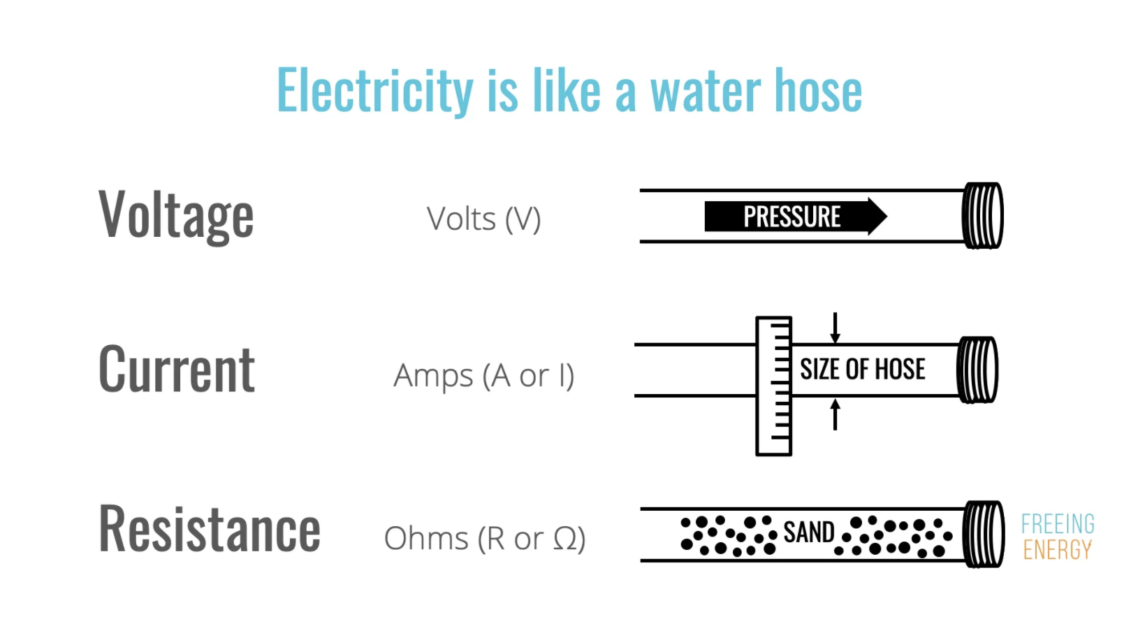
Image from freeingenergy.com
Current
Current is defined as the rate at which charge flows through a circuit. It's represented by the equation:
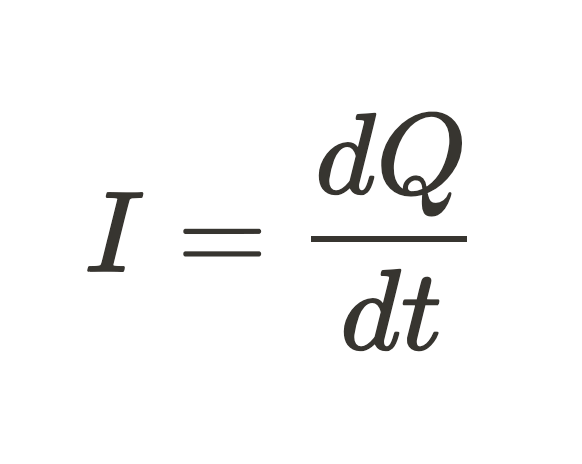
where I is the current (measured in Amps or milliAmps), Q is the charge passing a given point, and t is the time for the charge to pass through that point.
Conventional Current is defined as the direction a positive charge carrier will travel. This may seem strange to us since chemistry tells us that the electrons are the mobile part of the atom. Nevertheless, there are several advantages to choosing a positive direction, since that aligns with our choices in direction when it comes to electric fields and potential differences (see Unit 1).
On a microscopic level, current is also related to the drift velocity (v_d) of the individual charge carriers. Drift velocity can be thought of as the average velocity of each charge carrier as it moves through a wire. In the image below, we're looking at the path of the electron as it moves through a wire.
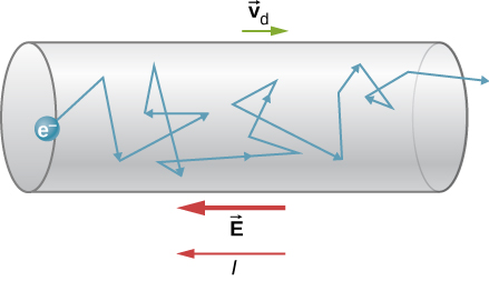
Image from openstax.org
We can imagine that the current in the wire would depend on the total number of charge carriers moving through the wire as well. A larger diameter wire would allow for more carriers. Combining these ideas together we can derive an equation for current.
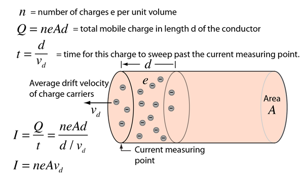
Image from hyperphysics
Current Density is a third way of describing the current in terms of the electric field, E, and the material it is traveling through. In this case, we define current density as a vector, J . We then relate the electric field to the current density through the equation below. (For a full derivation of this equation, check out this link)
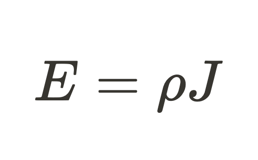
p is the proportionality constant between E and J and is called the resistivity. Resistivity describes how much a given material restricts the current. Resistivity depends on temperature (higher temperatures result in a higher resistivity, but most tables give values for 20 C)
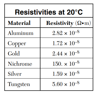
Data from NYS Physics Reference Tables
Resistance
While resistivity describes how much a material restricts the current, resistance (R) is much more useful for describing a circuit. It takes into account the length (L) and cross-sectional area (A) of the conductor as well.
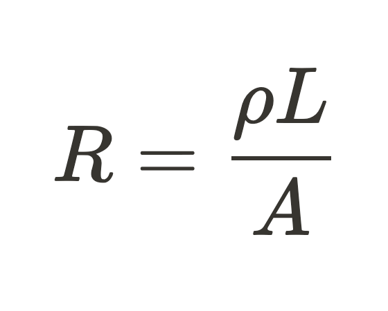
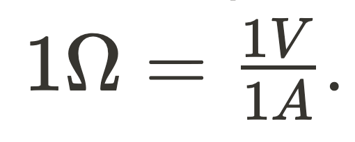
Resistance is defined as the opposition to current and can be a very useful feature when trying to design a circuit. For example, if the current gets too high in a cell phone, the battery starts expanding and can catch fire or explode. However, there are also times where you want to keep the resistance as low as possible (such as transmitting electricity from a power plant to people's homes). Resistance is measured in Ohms(Ω), where
Ohm's Law
The basic mathematical relationship between resistance and current is defined by Ohm's Law. Depending on your context, it's written one of 3 ways. It doesn't actually matter which one you're more familiar with since they're all the same equation.
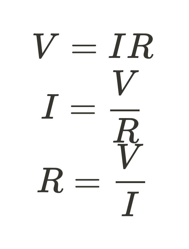
This law relates our three main circuit quantities in a nice simple equation. You will often see this represented in graphical form and be asked to infer if the device is Ohmic or non-Ohmic. As you can see in the graph below, an Ohmic device has a constant linear slope, while a non-Ohmic device does not. Sometimes a device can have an Ohmic region, then become non-ohmic.

Image from www.menihek.ca/
Power
Electric Power is the rate at which electrical energy is used in a circuit. While the reference tables only show one equation to calculate power, you can use Ohm’s law to tweak the equation to use whatever terms you are given (∆V, I, and R). We'll talk about this more in-depth with the next guide, but it's good to understand how it comes from Ohm's law in this section!

Circuit Symbols & Measuring Tools
To easily draw circuits, we use a variety of symbols to represent common components. Here are a few common ones, and there are many many more that are not used in AP Physics C EM (although if you become an electrical engineer you'll use them!). The ones that you can ignore are the DC power supply, junction of conductors, crossing conductors, microphone, loudspeaker, light emitting diode, fuse, alternating signal, thermistor, and light dependent resistor. You will also see the inductor in AP Physics C: Electricity & Magnetism, but you won't use it until you get to unit 5 😉.
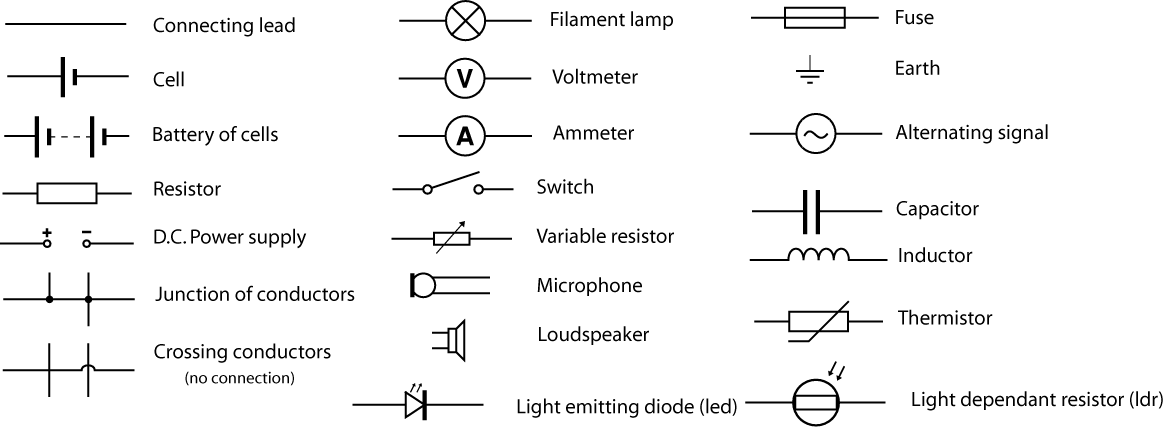
Image from wikimedia.org
The voltmeter and ammeter are two tools that are used to measure different aspects of an electrical circuit. The voltmeter is used to measure the potential difference (remember this from Unit 1!) between two points and is connected in parallel around the component being measured. It has a high internal resistance to avoid creating a short circuit when measuring. The ammeter, on the other hand, is used to measure the current flowing through a part of the circuit and is connected in series with the component being measured. Its internal resistance is low to accurately measure the current. It is important to be careful when using these tools and to ensure they are correctly configured, as incorrect use can lead to short circuits or faulty readings when doing lab work.
Drawing Parallel vs Series Circuits
There are two main ways to connect components in an electrical circuit: series or parallel. In a series connection, the components are arranged in a single line, and the current flows through one path. In a parallel circuit, the components are arranged with multiple paths for the current to flow through. This means that the current is divided between the available paths.
Practice Question
Image from AP Classroom
Choice B is correct. Because the resistance of a wire depends on

a longer length and smaller area will result in the greatest resistance.
Browse Study Guides By Unit
⚡️Unit 1 – Electrostatics
🔋Unit 2 – Conductors, Capacitors, Dielectrics
🔌Unit 3 – Electric Circuits
🧲Unit 4 – Magnetic Fields
⚛️Unit 5 – Electromagnetism
✍️Exam Skills- FRQ/MCQ
🙏Exam Reviews

© 2023 Fiveable Inc. All rights reserved.
